Design a current sensor - Weikewei - Professional FAE guidance
There are many methods for sensing current - all of which are somewhat cumbersome, at least compared to sensing voltage. The main reason for doing this is that since current flows instead of potential (such as voltage), we need to connect it in series with the circuit, not in parallel. For beginners, this is why there is such a significant difference in the performance of a multimeter when you switch it to the current range. The resistance of the instrument is now very low because it means it needs to be connected in series with a circuit. Therefore, if you accidentally touch the voltage source with the probe, it's like adding a short circuit to the voltage, and then the fuse in the instrument panel burns out. By the way, this is easy to do, and I have done it at least once with all my instruments.

Another popular method of detecting current is to connect a low value resistor in series with a circuit and measure the voltage drop across the resistor. This is very convenient when using small DC circuits, but not as convenient when using power circuits (120 volts or 240 volts in Europe). By the way, this is the way your instrument senses current, and fuses protect low value resistors, otherwise it may be wasted in unintentional current measurement errors.
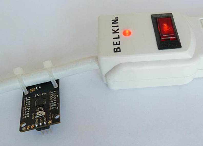
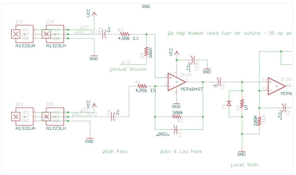
When using power circuits, transformers are usually used. Even if the electrician's clamp instrument works like this - although the principles may not be so clear. Only one conductor is inserted into the clamp table as a primary coil for one turn, forming the secondary winding of the transformer. Please note that if two conductors are inserted into the clamp, it is possible to read without reading, as the two wires have equal but opposite fields, which quickly cancels each other out.Many other small current transformers can also be used, but for hobbyists, connecting the circuit to a power source and finding a casing to accommodate the transformer can also be a bit troublesome. Recently, Hall effect current measurement chips have been used to measure current, but surprisingly, they are still connected to circuits and installed. Isn't it great if you can measure current without messing up the wiring or plugs? A small Hall effect sensor with linear output that can be used to measure magnetic fields. I think maybe this can be used to measure the current of ordinary wires, such as corduroy. You may be curious about the magnetic field that is equal to but opposite to the conductor at the other end of the light wire. The technique I use is to make the sensor physically close to one conductor rather than another, so that the magnetic field is' reasonable '.Two linear Hall effect sensors are surface mounted and packaged on adjacent conductors. They are directional, so that each sensor is closer to a wire in the cable. Then subtract the AC voltage from the sensor to eliminate common mode noise, and use a low-pass filter to filter out any signal greater than the power line frequency.Looking at the schematic diagram of the sensor input, we can see two sensors. In fact, there are four sensors in the schematic diagram, but only two sensors are filled at the same time. (We also want to try TO-92 format sensors to see if they are more suitable for this application.)The output voltage of the sensor is proportional to the current flowing in the power cable, and the output voltage of the sensor is introduced into the circuit through an ultrafiltration cap. These hats combine R1 and R3 to form a high pass filter - set in a corner at approximately 33 Hz. So sounds below this frequency will quickly disappear and will not enter the output. The low-pass filter formed by R1 and C1 has an angle of approximately 277hz (f=1/2 π R2 * C1), therefore high-frequency noise is also attenuated.

Operational amplifier enthusiasts will also recognize differential configurations, so the voltage of one sensor is subtracted from the voltage of another sensor. People may think that this will reduce the signal, but the key is that the sensor actually perceives a 180 degree phase difference in the signal, so the signal actually increases and other potential sources of noise are reduced. The output of the first operational amplifier is an AC waveform - the frequency is the same as the power line, but the voltage is proportional to the current flowing through the power line. This small AC signal then passes through C6, which eliminates any DC voltage offset, while passing through our power line signal. This signal is presented to the non inverting input of operational amplifier IC1D, which replicates a signal and introduces some gain (adjusted to R11+R13/R10), so you can see that a gain range from 1 to 10 is available. R9, C7, and R8 form a peak detector and store the height of the AC peak on capacitor C7. This voltage is buffered to the output terminal by the output amplifier IC1C.The capacitor in the peak detector slows down its response to eliminate any jitter. The response of sensors to the surrounding environment is quite slow, but I don't think most people are interested in rapidly changing signals when measuring current on power lines. Most users may only measure energy consumption 10 to 30 times per minute at most. Unfortunately, Hall effect sensors consume some electrical energy, so when powered at 5 volts, the sensor consumes approximately 20 milliamps. For users with very low power consumption (reading longer battery life), one strategy may be to power the sensor through a microcontroller (such as Arduino) pin and only sample the sensor once or twice per minute, then turn off the sensor between two samples. Sensors also require some time to start and stabilize (perhaps 3 seconds), so it is a good idea to do so at a relatively easy speed. We adjusted the sensor slightly in an attempt to bring it into the most useful range. If the nameplate on my electric kettle is reliable, the sensor can sense low-end 10 watts( 83ma@120V )Or high-end 1500 watts (12.5 a @ 120 volts). There is a significant noise floor issue 25 volts, as you may imagine sensors with so many gain applications. However, the jitter is quite small because so much filtering has also been applied.